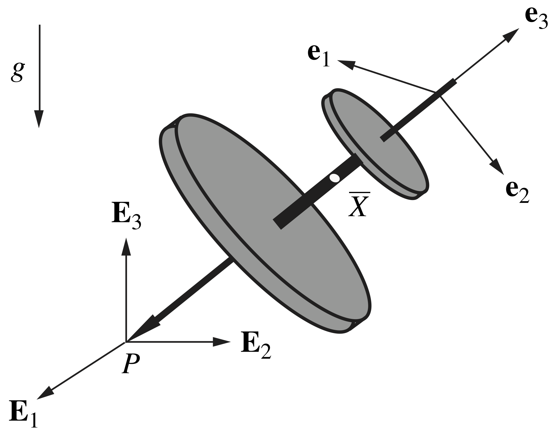
Referring to Figure 1 below, the Lagrange top is an axisymmetric rigid body whose point of contact ![]() with a horizontal surface is fixed. Such an object is referred to as the Lagrange top because Lagrange considered the dynamics of this body in his Mécanique Analytique (see [1]).
with a horizontal surface is fixed. Such an object is referred to as the Lagrange top because Lagrange considered the dynamics of this body in his Mécanique Analytique (see [1]).
Contents
Equations of motion
For the Lagrange top illustrated in Figure 1, we take its mass to be ![]() and assume the fixed contact point
and assume the fixed contact point ![]() is directly beneath the top’s mass center
is directly beneath the top’s mass center ![]() such that the relative position vector for
such that the relative position vector for ![]() is
is ![]() , where
, where ![]() is the top’s corotational basis. We may track the location of the top’s mass center using a set of Cartesian coordinates,
is the top’s corotational basis. We may track the location of the top’s mass center using a set of Cartesian coordinates, ![]()
![]() , and therefore the linear momentum of the top is given by
, and therefore the linear momentum of the top is given by ![]() , where
, where ![]() represents the space-fixed basis. The orientation of the top may be described by, say, a 3-1-3 set of Euler angles:
represents the space-fixed basis. The orientation of the top may be described by, say, a 3-1-3 set of Euler angles: ![]() ,
, ![]() , and
, and ![]() .
.

 .
.The Lagrange top’s longitudinal axis is assumed to be an axis of symmetry (i.e., the body is symmetric about the ![]() direction), and thus the top’s principal moments of inertia
direction), and thus the top’s principal moments of inertia ![]() and
and ![]() . We may then express the angular momentum of the top about its center of mass as
. We may then express the angular momentum of the top about its center of mass as ![]() , where
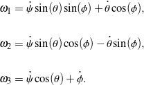
, where ![]() are the corotational components of angular velocity that, for a 3-1-3 set of Euler angles, are related to
are the corotational components of angular velocity that, for a 3-1-3 set of Euler angles, are related to ![]() ,
, ![]() , and
, and ![]() and their rates of change as follows:
and their rates of change as follows:
(1) 
The Lagrange top is subject to three integrable (holonomic) constraints of the form ![]() that arise from the fact that the contact point
that arise from the fact that the contact point ![]() is fixed, i.e., the velocity
is fixed, i.e., the velocity ![]() . These constraints relate the location of the mass center to the top’s orientation.
. These constraints relate the location of the mass center to the top’s orientation.
The equations of motion for the Lagrange top may be obtained by applying a balance of linear momentum and a balance of angular momentum with respect to the top’s center of mass: ![]() and
and ![]() , respectively, where the top’s weight and the reaction forces at the fixed contact point
, respectively, where the top’s weight and the reaction forces at the fixed contact point ![]() contribute to the net force
contribute to the net force ![]() and the net moment
and the net moment ![]() about the mass center. The resulting differential equations from applying the balance laws can then be expressed in the first-order form
about the mass center. The resulting differential equations from applying the balance laws can then be expressed in the first-order form ![]() for numerical integration in MATLAB, where we define the state vector
for numerical integration in MATLAB, where we define the state vector ![]() :
:
(2) ![Rendered by QuickLaTeX.com \begin{eqnarray*} && \mathsf{M}(t, \, \mathsf{y}) = \left[ \begin{array}{c c c c c c} (\lambda_{t} + m \ell_{3}^2) \sin(\theta) & 0 & 0 & 0 & 0 & 0 \\ 0 & \lambda_{t} + m \ell_{3}^2 & 0 & 0 & 0 & 0 \\ \cos(\theta) & 0 & 1 & 0 & 0 & 0 \\ 0 & 0 & 0 & 1 & 0 & 0 \\ 0 & 0 & 0 & 0 & 1 & 0 \\ 0 & 0 & 0 & 0 & 0 & 1 \end{array} \right], \\ \\ \\ && \mathsf{f}(t, \, \mathsf{y}) = \left[ \begin{array}{c} (\lambda_{a} - 2(\lambda_{t} + m \ell_{3}^2) ) \dot{\psi} \dot{\theta} \cos(\theta) + \lambda_{a} \dot{\theta} \dot{\phi} \\ (\lambda_{t} - \lambda_{a} + m \ell_{3}^2) \dot{\psi}^2 \sin(\theta) \cos(\theta) - \lambda_{a} \dot{\psi} \dot{\phi} \sin(\theta) + m g \ell_{3} \sin(\theta) \\ \dot{\psi} \dot{\theta} \sin(\theta) \\ \dot{\psi} \\ \dot{\theta} \\ \dot{\phi} \\ \end{array} \right]. \hspace{1in} \scalebox{0.001}{\textrm{\textcolor{white}{.}}} \end{eqnarray*}](https://rotations.berkeley.edu/wp-content/ql-cache/quicklatex.com-3a67e0cfced7993f95fee9b765f94269_l3.png)
Simulation and animation
For an arbitrary choice of initial conditions for the Euler angles and their rates of change, numerical simulation shows that the Lagrange top generally behaves like a spherical pendulum, assuming the top is allowed to fall below the horizontal. A typical example of this pendulum-like behavior is animated in Figure 2.
Figure 2. Animation of the pendulum-like behavior of the Lagrange top that is typical for an arbitrary choice of initial conditions. The path of the top’s tip is traced out to illustrate the top’s range of motion. The animation was recorded at 5x slower speed.
However, it is possible for the Lagrange top to undergo a steady motion in which it precesses and spins at constant rates (that is, ![]() and
and ![]() , respectively, are constant) while at a fixed nutation angle
, respectively, are constant) while at a fixed nutation angle ![]() under the following condition:
under the following condition:
(3) ![]()
An animation of a representative steady motion is shown in Figure 3.
Figure 3. Animation of the Lagrange top undergoing a steady motion in which the trajectory of the top’s tip is a circle. The animation was recorded at 5x slower speed.
The Lagrange top features several conservations. It can be shown that the top’s simulated motion conserves two components of the top’s angular momentum with respect to the fixed contact point ![]() :
: ![]() and
and ![]() . In addition, the top’s total mechanical energy
. In addition, the top’s total mechanical energy ![]() is conserved:
is conserved:
(4) ![]()
Downloads
The animations in Figures 2 and 3 were generated using the following MATLAB code: